
UK Hydraulic Engineering Guide
Hydraulic Cylinder Pressure Intensification and Thermal Locking
The practical value of a technical article is measured by whether it helps a buyer ask better questions before a drawing is approved. This article examines hydraulic cylinder pressure intensification for lifting equipment, clamping systems, cranes and machines with pilot-operated load holding in the United Kingdom. The supplied catalogue provides a real hydraulic cylinder family, model code and dimensional reference, while the subject-specific discussion explains which facts still require project validation. A hydraulic cylinder converts fluid pressure into linear movement, but the machine result depends on pressure, effective area, linkage leverage, speed, alignment, valves, fluid condition and the stiffness of the surrounding structure. The catalogue row below is evidence for its stated model only; it does not prove that the example is suitable for another machine or that its materials, seals, certificates or compatibility are the same. The design route should record the duty, identify the worst credible load, check the interface at every position and place the final requirements on an approved drawing. That approach is particularly important for UK buyers who may be replacing an older actuator with limited documentation, integrating a new hydraulic cylinder into exported equipment or comparing quotations from suppliers that describe scope in different ways.
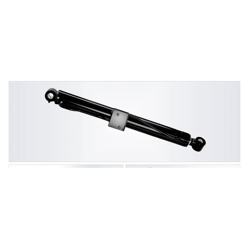
Hydraulic Cylinder Evidence Boundary: catalogue-derived values below come from supplied page 21. Materials, seal compound, certificates and compatibility are not stated. The approved order drawing controls production.
Hydraulic Cylinder Catalogue Technical Reference
| Catalogue family | Catalogue model | Bore / rod / stroke notation | Working pressure | Maximum withstand pressure | Stroke / trip | Installation distance | Weight |
|---|---|---|---|---|---|---|---|
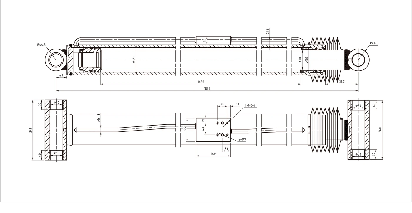
| Folding boom angle cylinder | HCYY11112011 | Φ100×Φ80×1458 | 21 MPa | 32 MPa | 1458 mm | 1899 mm | 137 kg |
Read the model row as a source reference for the stated catalogue configuration. Verify bore, rod, stroke, installation distance, mounting, ports and interfaces on the drawing. Working pressure and maximum withstand pressure are different fields and must not be treated as interchangeable operating targets.
Hydraulic Cylinder Working Principle, Force and Area Ratio
The central technical question is how unequal piston areas, trapped oil and external load can produce rod-side pressure that is higher than the applied cap-side pressure, and how temperature changes can raise pressure in an isolated volume. The theoretical push force of a hydraulic cylinder begins with pressure multiplied by the full piston area, F=P×πD²/4, while theoretical pull force uses the annular area, F=P×π(D²−d²)/4. Those expressions do not include seal friction, line loss, valve back pressure, linkage disadvantage or acceleration. For hydraulic cylinder pressure intensification, the force calculation must be connected to bore area, annular area, load direction, applied pressure, back pressure, valve leakage, trapped volume, hose expansion, fluid thermal expansion, relief location and expected temperature range. A hydraulic cylinder can be strong enough at one point in the stroke and inadequate at another because the lever arm changes. It can also meet the static load and still suffer from shock, instability or heat when the cycle repeats. Working pressure, maximum withstand pressure and relief setting are separate concepts. The maximum value printed in a catalogue is not an invitation to run continuously at that pressure. Record both chamber pressures when area ratio or load direction can create a local pressure that differs from the pump gauge. The result of the calculation should be a controlled load case, including normal duty, occasional peak events, fault conditions and the method used to keep people clear of stored hydraulic and mechanical energy.
Hydraulic Cylinder Design Inputs and Calculation Boundaries
A disciplined worksheet for hydraulic cylinder pressure intensification should contain bore area, annular area, load direction, applied pressure, back pressure, valve leakage, trapped volume, hose expansion, fluid thermal expansion, relief location and expected temperature range. Bore determines cap-end area and oil demand; rod diameter changes pull force, buckling resistance and area ratio; stroke describes travel but not the overall closed or open length. Flow controls speed through v=Q/A, yet actual movement also reflects oil compressibility, hose expansion, valve timing and acceleration. The hydraulic cylinder mounting arrangement decides whether load reaches the barrel and rod axially or creates bending. Pin diameters, bearing widths, bracket clearances and articulation angles therefore belong beside pressure and flow in the specification. The designer should check the full envelope with hoses, guards, sensors and neighbouring structure included. A replacement hydraulic cylinder should be measured from stable datums with the old machine safely supported. A new-build hydraulic cylinder should be evaluated through the complete motion model, not only a retracted drawing view. Where calculations use an assumed efficiency, shock factor, friction value or duty factor, identify it as an engineering assumption and retain enough margin for measurement uncertainty. A supplier can then review the same inputs instead of guessing what the buyer meant by heavy duty.
Hydraulic Cylinder Construction, Materials and Failure Risks
Construction and material decisions must follow the service environment. The supplied catalogue does not state the tube grade, rod grade, seal compound, bearing material, weld procedure or coating system, so those facts remain unknown until an approved material schedule or drawing states them. Common hydraulic cylinder proposals may use pressure-rated tube, rod, ports, seals, hoses and valve bodies must be selected for the highest credible local pressure, not only the normal pump setting. For hydraulic cylinder pressure intensification, material selection should also address rod-side overpressure, extruded seals, damaged hoses, cracked manifolds, unexpected movement during service, valves that cannot open against trapped pressure and thermal pressure rise in parked equipment. A harder rod coating cannot compensate for side load, and a premium seal cannot survive incompatible fluid, excessive temperature or a damaged surface. Corrosion protection has to cover the parts that remain exposed during the real stroke, not just the painted barrel. Bearings and pins require a defined lubrication or maintenance-free strategy; the two approaches must not be mixed casually. Welded attachments need controlled geometry and inspection, while threaded or bolted components need a defined retention method. The hydraulic cylinder supplier should state proposed materials, surface finish, sealing system, fluid compatibility and test scope. The buyer should state cleaning chemicals, pressure washing, fertiliser, salt, temperature, storage and expected maintenance access. That exchange turns an attractive component description into a reviewable engineering proposal.
Hydraulic Cylinder Valves, Controls and Related Components
The hydraulic cylinder cannot be separated from the circuit that controls it. For this topic, the relevant control elements include cross-port relief valves, thermal relief valves, load-holding valves with defined pilot conditions, service bleed points, pressure gauges and safe mechanical supports. Valve selection affects speed, pressure, drift, heat and the behaviour of suspended or overrunning loads. A pilot-operated check valve can hold position, yet it may trap pressure that requires a deliberate service method. A counterbalance valve can control lowering, but pilot ratio, back pressure, setting and installation location influence stability. Flow controls may create heat or pressure intensification if used without considering load direction and area ratio. Position sensors improve control only when their scaling, wiring and fault response are validated. Relief protection should be located so that the vulnerable chamber and connecting line are actually protected. The hydraulic cylinder ports, hose sizes, adapters and bend radii must carry the calculated flow without excessive pressure drop. Related items such as thermal relief valves, counterbalance valves, pilot-operated checks, pressure transducers, test couplings, hoses, accumulators, mechanical props and crane safety systems belong in the same system review. A well-made hydraulic cylinder cannot correct a blocked make-up path, contaminated valve, weak bracket or controller command that drives the mechanism into a hard stop.
Hydraulic Cylinder Installation and Commissioning Method
Installation should convert the approved drawing into a clean, aligned and testable assembly. The planned method is to identify every isolated oil volume, confirm relief paths, place test points on both sides, protect gauges, avoid heating trapped lines during welding or painting and verify depressurisation before loosening fittings. Before work begins, lower or restrain the load, isolate energy, prove pressure is released and keep personnel out of the rod travel and leak-jet zones. Protect ports until the connection is ready. Flush new hoses and pipes, clean preserved surfaces with compatible products and inspect pins, bearings and brackets rather than assuming the old hardware is reusable. The hydraulic cylinder should move freely through its intended arc without the mounting lugs being pulled into alignment by the pin. Fill and bleed at low pressure with bleed points arranged so air can escape. Extend and retract slowly, listening for knocking and watching for hose movement, bracket deflection and contact with external stops. Verify both chamber pressures, the relief setting, load-holding behaviour and the commanded speed. A low-pressure leak and movement check should precede the working-load test. Record the final pin arrangement, port orientation, hose routing, sensor readings and test results so future maintenance teams know how the hydraulic cylinder was commissioned.
Hydraulic Cylinder Maintenance, Troubleshooting and Safe Work
Maintenance should look for evidence rather than wait for a visible oil puddle. The relevant plan is to record both chamber pressures, inspect for seal extrusion, investigate hoses that become rigid while parked, test relief functions, watch for unexpected rod movement and treat stored energy as present until measured otherwise. Rod condition, wiper performance, leakage, pin play, bearing temperature, coating damage, hose abrasion and valve response reveal different parts of the failure chain. A drifting hydraulic cylinder may have piston-seal bypass, valve leakage, external load movement, thermal effects or a position-sensor problem; isolating the cause requires pressure and movement data. A noisy hydraulic cylinder may be side loaded, aerated, cavitating or striking an end stop. Hot oil may come from throttling, an undersized line, high cycle rate or inefficient pressure control rather than the cylinder alone. Never search for a high-pressure leak with a hand. UK safety guidance treats injection injury as a medical emergency and emphasises the stored energy present in hydraulic systems. Use cardboard or an approved detector from a safe position, mechanically support the load and depressurise every trapped chamber before loosening a fitting. Trend observations against hours or cycles so a gradual change can be addressed before it becomes an unplanned outage.
Illustrative UK Hydraulic Cylinder Machinery Case
Illustrative composite case: an illustrative Northern England lifting fixture where the pump relief appeared correct but annular-side pressure exceeded expectations because of area ratio and trapped return pressure. The engineering team began by recording the machine load, linkage geometry, closed length, open length, pin dimensions, port threads, hose path and normal pressure. They compared the measurements with a catalogue example but did not treat the catalogue model as automatically compatible. The review then concentrated on how unequal piston areas, trapped oil and external load can produce rod-side pressure that is higher than the applied cap-side pressure, and how temperature changes can raise pressure in an isolated volume. A marked-up drawing showed the interfaces that had to remain unchanged and separated them from features that could be redesigned. Pressure and flow measurements were taken through a representative cycle, and the hydraulic cylinder was checked at the least favourable linkage position rather than at the easiest point to access. The quotation request included materials as proposals, a defined inspection and test scope, spare sealing parts and a drawing-approval hold point. During commissioning, the team used low pressure, verified free articulation and recorded both chamber pressures before moving to working load. This case is not a verified customer endorsement or a claim about a named project. It demonstrates how a UK machinery team can reduce risk by replacing assumptions with measurements, controlled drawings and test evidence.
UK Hydraulic Cylinder Applications and Agricultural Machinery Parts
The United Kingdom operating context changes practical priorities without changing the physics. equipment moving between cold outdoor storage and warm production areas can experience significant temperature change in closed hydraulic volumes. Equipment may move between outdoor storage, road travel, heated workshops and pressure-washing areas. Imports and replacement programmes also benefit from unambiguous metric dimensions, port designations, drawing revisions and packaging instructions. For hydraulic cylinder pressure intensification, buyers in England, Scotland, Wales and Northern Ireland should state the actual delivery location, expected service access, environmental exposure and documentation language. A hydraulic cylinder intended for agricultural duty may need protected pins, robust wipers and related farm components such as PTO shafts, gearboxes, chains and hydraulic couplers. A hydraulic cylinder for precision machinery may instead prioritise low-speed behaviour, sensing, stable temperature and traceable inspection. Those differences should appear in the quotation request rather than in generic marketing language. Local availability should never be assumed; ask the supplier to state production lead time, transport protection, spare-part supply and what information will be retained for future replacement. This provides useful regional relevance without inventing stock, offices or service coverage.
Hydraulic Cylinder Standards, Evidence Boundary and Engineering Approval
Current official context supports a documented selection process. UK safety guidance emphasises stored hydraulic energy and the severity of injection injury, supporting measured depressurisation and mechanical load restraint before intervention. Standards define selected dimensions, terminology, quality frameworks or safety expectations, but a standard number alone does not prove that a catalogue model is certified, interchangeable or suitable for the machine. The hydraulic cylinder purchase specification should name the exact standard edition and the clauses or dimensions that matter, then require the supplier to state conformity or exceptions. For welded construction, production-quality criteria still need a fitness-for-purpose design and fatigue review. For lifting machinery, UK duties for planning, inspection, maintenance and thorough examination belong to the equipment owner and competent persons; a component page cannot replace that assessment. The supplied catalogue remains the source of record for the model row shown in this article. Connected engineering guides and current official web pages provide background methodology only. The final hydraulic cylinder pressure, materials, seals, welding, mounting, sensor arrangement, valve settings and compatibility require engineering approval and an approved order drawing.
Custom Hydraulic Cylinder Manufacturing and RFQ Scope
A useful request for quotation gives the manufacturer enough information to design and price the correct scope without guessing. Include the machine function, load cases, pressure trace, flow, bore and rod targets if already calculated, stroke, closed and open dimensions, mount geometry, pin and bearing details, ports, hose orientation, fluid, temperature, contamination, cycle rate, testing, inspection, documentation, packaging, annual quantity and delivery location. Ask for a drawing before production and identify which dimensions are controlled by the machine. For hydraulic cylinder pressure intensification, add the topic-specific inputs: bore area, annular area, load direction, applied pressure, back pressure, valve leakage, trapped volume, hose expansion, fluid thermal expansion, relief location and expected temperature range. Ask the supplier to separate catalogue-exact facts from proposed materials and engineering assumptions. Custom capability may include alternative mounts, ports, sensors, valve blocks, coatings, seal systems and packaging, but those options should be confirmed rather than advertised as standard. The quotation should identify included accessories, spare seals, inspection records and any excluded machine-side work. A hydraulic cylinder can then be evaluated on controlled technical scope and lifecycle support rather than unit price alone. The form below is intentionally brief; the detailed RFQ can be attached after initial contact.
Hydraulic Cylinder Advantages When the Specification Is Controlled
A properly specified hydraulic cylinder provides compact linear force, flexible mounting and controlled motion within a defined machine envelope. The useful advantages come from matching bore, rod, stroke, pressure, speed, bearings, seals, ports and valves to the actual duty rather than selecting by appearance. Drawing control supports replacement fit and inspection. Application-specific wipers, coatings and bearings can improve resistance to the documented UK environment. Sensors and load-holding functions can be integrated where the risk assessment and control concept require them. Related products such as thermal relief valves, counterbalance valves, pilot-operated checks, pressure transducers, test couplings, hoses, accumulators, mechanical props and crane safety systems can be reviewed as one system so the cylinder is not undermined by weak brackets, undersized hoses or unsuitable controls. These are engineering benefits of a controlled specification, not unsupported claims that every catalogue model contains every option.
Hydraulic Cylinder Engineering Review Table
| Review area | Inputs to record | Decision rule |
|---|---|---|
| Hydraulic Cylinder Load and Force | Pressure, full-bore area, annular area, linkage leverage and acceleration | Check the complete motion, not one static position. |
| Hydraulic Cylinder Speed and Flow | Effective area, flow, line loss, valve capacity and oil compressibility | Extension and retraction may have different speeds. |
| Hydraulic Cylinder Mechanical Interface | Pin centres, mount width, articulation, bracket stiffness and side load | The hydraulic cylinder should move the load, not guide a distorted frame. |
| Hydraulic Cylinder Control and Safety | cross-port relief valves, thermal relief valves, load-holding valves with defined pilot conditions, service bleed points, pressure gauges and safe mechanical supports | Document the normal, emergency and fault states. |
| Hydraulic Cylinder Environment and Service | equipment moving between cold outdoor storage and warm production areas can experience significant temperature change in closed hydraulic volumes | State the fluid, temperature, contamination and cleaning method. |
Three Illustrative Hydraulic Cylinder Review-Style Statements
The statements below are layout examples and are not verified endorsements, named customers or evidence of a completed sale.
“The drawing review exposed an interface assumption before the hydraulic cylinder reached the machine.”
“Pressure, mounting, testing and spare parts were placed in one quotation scope, which made comparison more useful.”
“Low-pressure commissioning and recorded pin-centre dimensions reduced uncertainty during installation.”
Questions UK Buyers Commonly Ask
How can a UK lifting equipment buyer request a quote for hydraulic cylinder pressure intensification?
Send the machine function, load case, pressure, flow, stroke, closed and open dimensions, mount details, port orientation, fluid, environment, cycle rate, quantity and delivery location. A marked-up drawing and clear photographs reduce uncertainty before quotation.
What hydraulic cylinder pressure intensification price information should an England machinery team send to a supplier?
Ask for a scope that separates the cylinder, mounts, valves, sensors, testing, inspection records, packaging, spares and exclusions. Price comparisons are useful only when the pressure, materials, dimensions and documentation are reviewed on the same basis.
Which hydraulic cylinder pressure intensification supplier documents matter for equipment operating in Scotland?
Request the approved dimensional drawing, material and seal proposal, test plan, identification method, maintenance information and any named standard requirement. Do not assume certification, interchangeability, local stock or a service life that the supplier has not stated.
Where can a Welsh maintenance team compare hydraulic cylinder pressure intensification replacement dimensions before ordering?
Measure the existing machine and hydraulic cylinder from stable datums, then compare pin centres, closed length, open length, stroke, pin diameters, mount widths, port thread and port clocking with the proposed drawing. Photographs alone cannot control fit.
When should a Northern Ireland buyer request a revised hydraulic cylinder pressure intensification cost?
Request a revision whenever the load, pressure, stroke, mounting, ports, quantity, sensor, valve, testing, coating, documentation, packaging or delivery conditions change. A current quotation prevents an old assumption from becoming a production requirement.
Why should a UK equipment manufacturer approve the hydraulic cylinder pressure intensification drawing before production?
The approved drawing defines the interfaces that determine fit, motion and inspection. It gives the buyer and supplier one controlled reference for manufacture, installation, future replacement and management of any later design change.
Request a Hydraulic Cylinder Engineering Quote
Send the machine duty, load, pressure, flow, stroke, mount dimensions, ports, environment, quantity and delivery requirement. Detailed drawings and technical files can follow the initial enquiry.